After converting my HP 6632B to 66332A like I described in a previous post, I now wanted to test the new features.
Therefore I converted the example program from the "Pulse Measurement Queries" section of the programming guide to a simple python script for my GPIB Adapter and the Instrumentkit library. It basically sets the supply to 1V, 1A current limit and the triggerlevel to 2A positive Edge. When triggered, it should then measure 2000 samples with one sample every 46.8 us. You can see it below:
import instruments as ik

psu = ik.hp.HP6632b.open_gpibusb("/dev/ttyUSB0", 4)

#Set 1V, 1A current limit
psu.reset
psu.voltage = 1
psu.current = 1
psu.output = True

#Set meter to ACDC
psu.sendcmd("SENS:CURR:DET ACDC")
#Set to high current range
psu.sendcmd("SENS:CURR:RANG MAX")
#Set pulse trigger
psu.sendcmd("TRIG:ACQ:SOUR INT")
#Acquire current reading
psu.sendcmd('SENS:FUNC "CURR"')
#Triggerlevel 2A
psu.sendcmd("TRIG:ACQ:LEV:CURR 2")
#Positive edge trigger
psu.sendcmd("TRIG:ACQ:SLOPE:CURR POS")
#.05A Hysteresis
psu.sendcmd("TRIG:ACQ:HYST:CURR .05")
#Set sample interval
psu.sendcmd("SENS:SWE:TINT 46.8E-6")
#Number of samples
psu.sendcmd("SENS:SWE:POIN 2000")
#Set Number of Samples before trigger
psu.sendcmd("SENS:SWE:OFFS:POIN -20")
#Initiate trigger
psu.sendcmd("INIT:NAME ACQ")

print("Waiting for Trigger")

input("Press enter to continue: ")

print("Fetching Data ...")

#Print Data
print(psu.query("FETCH:ARRAY:CURR?"))
To perform the test, I connected a 10 m\(\Omega\) Resistor with the Output already turned on. The measured values from the supply can be seen in Fig.1
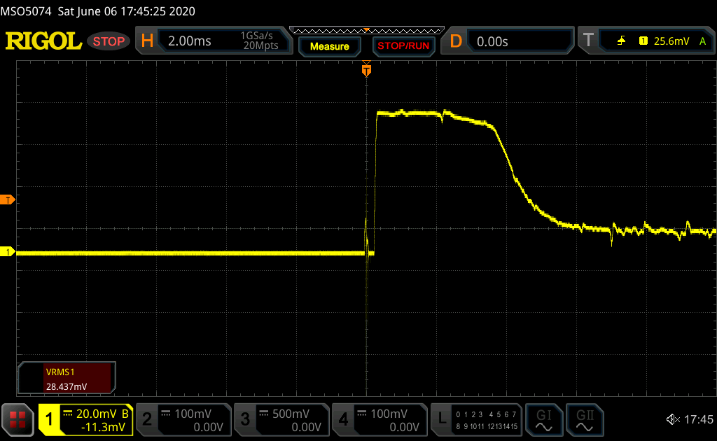
For comparison I measured the voltage over the resistor with my MSO5000 scope, which you can see in Fig.2.

You can clearly see that the measurements are identical, which shows that the 6632B is working fine as a 66332A.
Interestingly it also shows, that it supplies a charge of about 30 mC before it goes into CC-mode.
