Recently, I have bought a defective Marconi IFR 2023A signal generator from eBay. The listing said "parts or repair unit" and that the power supply is missing.
Missing power supply
The Marconi needs 5V,+/-12V and 24V, therefore I replaced the missing power supply with a Meanwell RQ-125D. The current requirements are listed in the table below.
| Voltage | Current Req. | RQ-125D |
|---|---|---|
| +5V | 2.8 A | 8 A |
| +12V | 2.3 A | 2.5 A |
| -12V | 0.6 A | 0.5 A |
| +24V | 0.6 A | 2 A |
Dim display
After that, I was able to turn the unit on, unfortunately the display was very dim, and everything was barely visible. In the menu the contrast setting was at default (127), after increasing it to 255 it was much better, so there must be something wrong with the contrast setting. I checked the contrast setting circuit and found out that the control voltage was very low, even on the highest setting.
The brightness is set by IC34 DAC to max. 3V. The level is then shifted by a pull-up resistor to the 5VA rail to max. 5V. But 5VA was only 3V. This was caused by the series inductor L2, having a very high resistance. This inductor is used in an LC Filter for the 5VA rail, to remove noise from the 5V rail. After replacing it, the display was looking good again.
21V rail unstable
Level 2 password sniffing
The level 1 password was default 1234, but the level 2 password has been changed from default 123456 to an unknown combination. Some people described, that they have received a Master password from Aeroflex, the IFR Marconi successor, after providing the serial number, but this hasn't worked for everyone. Fortunately the marconi ist just a signal generator and not a cryptographic device, so the password is read unencrypted from the memory and is compared to the password that you enter. The process to sniff the password from the IC7 EEPROM is described in this groups.io thread from the marconi usergroup. I found it easiest to hook up the LA-probes to the data D0-D7 lines on the GPIB Controller IC56, because it is a fairly large DIP package.
Error 508: Amplitude mod unleveled
The generator was working almost normally, but the modulated Waveform clipped at some frequencys under 400 MHz and on the entires range above. At some of these frequencys error 508 showed up on the display. Therfore I first checked if the modulation signal is generated correctly. The waveform (sine, triangle or square) is generated by a DSP, and the offsetvoltage is provided by a DAC. The signal gets predistorted to compensate for the nonlineararity of the schottky envelope detector in the PIN-Modulator control loop. But this part of the circuit was working fine.
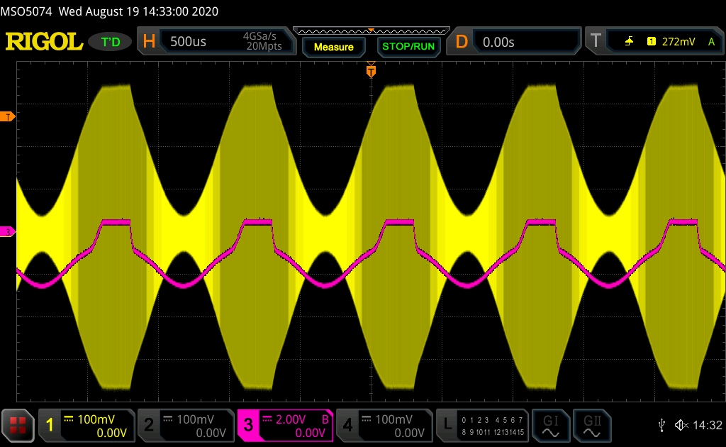
The service manual mentions, that there could be a problem in the filter section but the error was not present in just one specific bands, so the filter section could not be the problem. The signal level going into the Modulator was also ok, so the problem had to be in the Modulator section itself. In the screenshot below, the frequency is set to 200 MHz with 1kHz 80% AM Modulation, the pink trace shows the control voltage of the PIN Modulator. The control voltage is clipping, which could mean that there is not enough gain provided by the amplifiers TR510, TR506 and TR508 to compensate for the losses. So lets take a closer look at these amplifiers.

Each of them is equipped with an active bias control which keeps the bias current stable and compensates for temperature changes. Below you can see the simplified schematic in LTspice. For the dc analysis, we can ignore the capacitors and inductors and the fact that the RF Transistor is replaced with a simple BC847 npn.
The divider formed by R1 and R2 controls the base voltage of Q1, which therefore sets the collector voltage of Q2 to the 7.8 V created by the divider. The diode is used to compensate the temperature coefficient of the base-emitter junction of Q1. The collector current is set by R4 to about 29 mA with \(I_C={V_{CC}-V_{CE} \over {R_{4}+11.75 \Omega}}\).
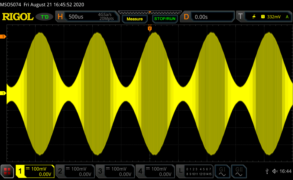
I measured Vce at 7.8 V but Vbe was 1.8 V, instead of the expected 0.7-0.8V. The absolute Maximum for the AT-42086 Vbe is 1.5V! I also tried to measure the gain with an active probe, but there was no gain, TR506 and TR508 were completely dead. Unfortunately the AT-42086 is obsolete since many years, but I found an ebay seller which offers some genuine NOS parts. After replacing the dead parts the unit is working fine again, and error 508 disappeared. For comparison you can see the working amplitude Modulation with the same settings (200 MHz with 1kHz and 80%) in the picture below.

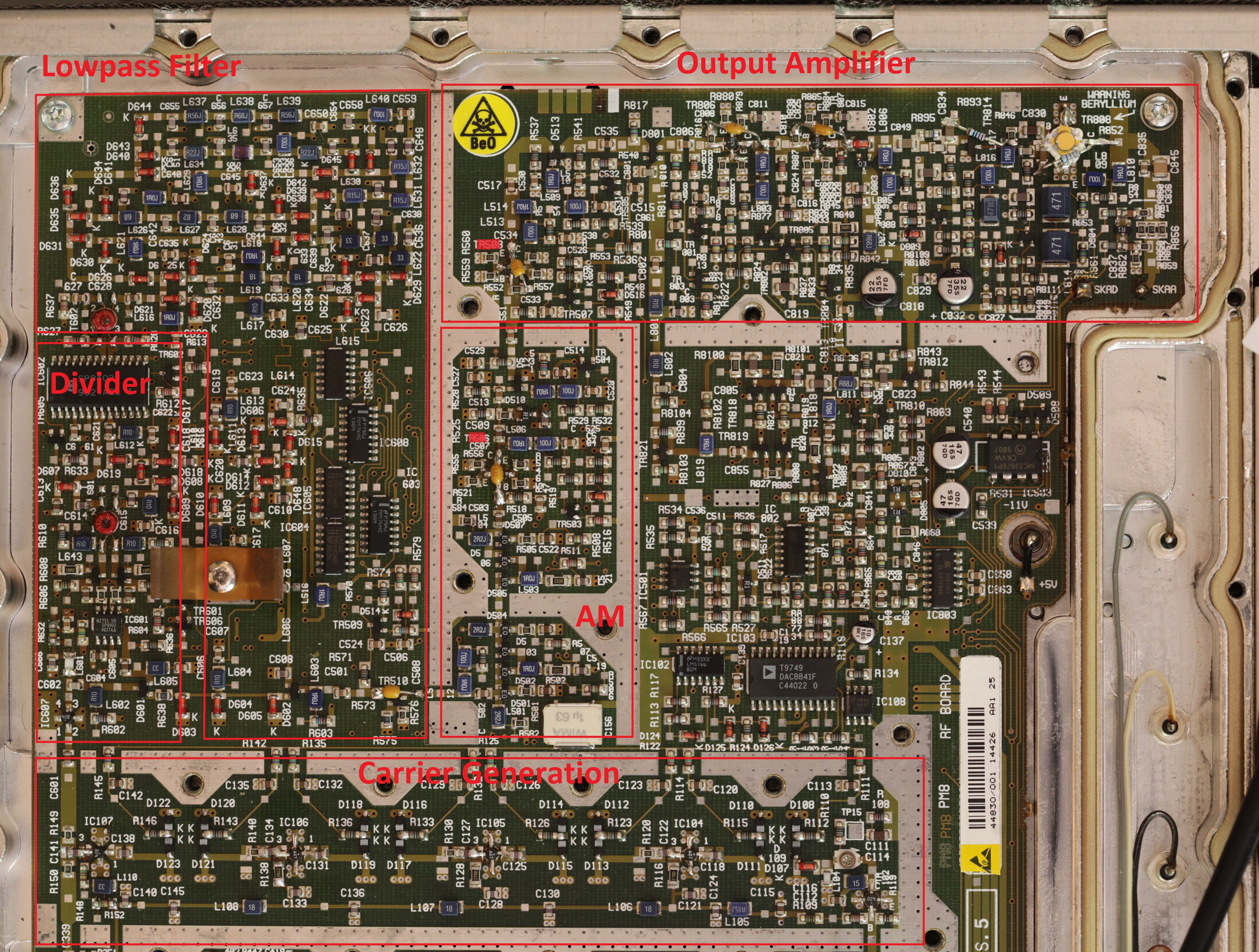
In the picture below, I have marked the blocks that I tested on the RF board from the VCO to the RF output.

Repair Costs
| Part | Ref. Des. | Price |
|---|---|---|
| RQ-125D | PSU | 39 € |
| AT-42086 | TR506, TR508 | (10pcs) 15 € |
| Total | 54 € |
Downloads
Firmware IC5 v1.06: IFR2023A_IC5_1.06
Attention: The new service manual has a higher resolution, but contains more errors!
New Service manual: ko4bb.com
Old Service manual: ko4bb.com
